
Drainage System Design: A Complete Planning Guide
Drainage system design is the systematic planning and engineering of pipe networks, traps, vents, and discharge facilities that safely convey wastewater and stormwater away from properties. The industry term for this discipline is stormwater and sanitary drainage engineering, though “drainage system design” is the phrase most planners and property owners use day to day. A well-designed system follows codes like the International Plumbing Code (IPC) and Uniform Plumbing Code (UPC), applies gravity-flow gradients, and separates sanitary from storm flows. Get it wrong, and you face flooding, structural damage, and serious health risks from sewer gas exposure.
What is drainage system design, and why does it matter?
Drainage system design is a planned network of pipes engineered to safely move wastewater and stormwater away from a structure while preventing flooding, structural damage, and health hazards. The system does not work by accident. Every pipe slope, fitting angle, and vent location is calculated to keep flow moving at the right speed.
Poor drainage is not just inconvenient. Saturated soil increases hydrostatic pressure against foundations and retaining walls, which can cause cracking or outright failure. Sewer gases released from broken trap seals create indoor air quality problems that affect occupants directly. The importance of drainage design becomes clear the moment any one of these failures appears.
Three regulatory codes govern most American drainage installations: the IPC, the UPC, and local municipal amendments. Los Angeles, for example, layers its own requirements on top of the UPC. Knowing which code applies to your project is the first step before any pipe is sized or slope is calculated.
What are the fundamental principles and components of drainage design?
Modern drainage design includes three primary interconnected subsystems: sanitary drainage, storm drainage, and vent piping. Each serves a distinct purpose, and none can be omitted without degrading the whole system.
The physical components of a complete system include:
- Pipes: The main conveyance element, typically PVC, ABS, or cast iron depending on the application and local code.
- Traps: Water-sealed U-shaped fittings that block sewer gases from entering occupied spaces. Every fixture requires one.
- Vents: Pipes that run to the roof to balance atmospheric pressure and protect trap seals.
- Inspection chambers: Required at pipe junctions and direction changes to allow maintenance access without demolition.
- Soak pits and discharge points: Terminal structures where treated or filtered water re-enters the ground or a public sewer.
Gravity flow drives the entire system. Pipes are laid at slopes between 1:40 and 1:100 to maintain self-cleansing velocity, which keeps solid waste suspended and moving rather than settling and blocking the pipe. A slope that is too flat lets solids drop out. A slope that is too steep lets liquid outrun solids, leaving residue behind and causing odors.
Long-radius bends outperform sharp 90-degree angles in drainage applications. Sharp angles create turbulence, slow flow, and give solids a place to accumulate. Wherever a direction change is unavoidable, two 45-degree fittings in sequence perform better than a single 90-degree elbow.

Vent piping balances atmospheric pressure and protects trap seals throughout the system. Vent stacks protrude through roofs, which requires coordination with roofing and structural teams to minimize impact. A missing or undersized vent stack is one of the most common causes of gurgling drains and slow flow in residential buildings.
Pro Tip: Never reduce pipe diameter in the direction of flow. Drainage pipes must stay the same size or increase as they move toward the main sewer. Reducing diameter creates a bottleneck that causes backups under peak load.
How do designers calculate and size drainage systems effectively?
Accurate sizing is the technical core of drainage system design. Undersized pipes back up under peak load. Oversized pipes run at low velocity, allowing solids to settle and creating chronic maintenance problems.
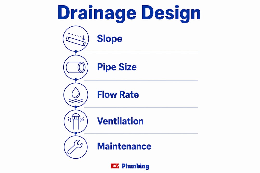
The standard sizing method for sanitary systems uses Drainage Fixture Units (DFU), a weighted measure of each fixture’s discharge load. A toilet carries a higher DFU value than a lavatory because it discharges more volume in a shorter time. Designers add up all DFU values on a branch, then reference pipe sizing tables in the IPC or UPC to select the correct pipe diameter.
Storm drainage sizing follows a different path:
- Determine the design storm. Storm drains are sized for 100-year storm rainfall intensity in most jurisdictions. This represents the worst-case runoff event the system must handle.
- Calculate the drainage area. Measure the roof, paving, and landscape areas that drain to each inlet.
- Apply a runoff coefficient. Impervious surfaces like concrete produce more runoff than grass. The coefficient adjusts raw rainfall data for surface type.
- Size the pipe. Use the rational method or local drainage tables to match pipe diameter and slope to the calculated flow rate.
- Set invert elevations. Invert elevations define the inside bottom of each pipe at every junction. Errors here cause infiltration and capacity loss over time.
The relationship between pipe slope and capacity is not linear. Doubling the slope does not double the flow capacity. A 100mm pipe at 1:80 slope carries a specific volume per second. Changing the slope by even 0.5% shifts that capacity meaningfully. This is why field installation must match design drawings exactly.
| Pipe diameter | Typical DFU capacity | Minimum slope |
|---|---|---|
| 50mm (2 in) | Up to 3 DFU | 1:40 |
| 75mm (3 in) | Up to 20 DFU | 1:50 |
| 100mm (4 in) | Up to 160 DFU | 1:80 |
| 150mm (6 in) | Up to 360 DFU | 1:100 |
A pipe laid with inaccurate slope can reduce a system designed for a 10-year storm event to functioning effectively only at a 2-year level. That gap represents a significant flood risk for the property.
What are common subsurface and specialized drainage solutions?
Subsurface drainage controls groundwater and soil moisture that surface drains cannot reach. French drains and blanket drains reduce hydrostatic pressure and prevent soil saturation that causes retaining wall and slope failures. These systems are often the most underfunded part of a site drainage plan, yet their failure leads to the most expensive structural repairs.
Key subsurface drainage components and their roles:
- French drains: A perforated pipe wrapped in geotextile fabric, set in a gravel trench. Water enters the pipe through perforations and flows to a discharge point by gravity.
- Blanket drains: A layer of granular material placed behind a retaining wall to intercept groundwater across a wide area before it reaches the wall face.
- Chimney drains: Vertical drainage elements within an embankment that intercept seepage moving horizontally through the soil.
- Geocomposite drainage panels: Factory-made sheets combining a drainage core with a geotextile filter. They replace gravel blankets in tight spaces and reduce installation time.
- Weep holes: Openings through retaining walls that allow water to exit. Clogged weep holes and missing filters are primary failure modes in geotechnical drainage. They work only when kept clear and protected by a filter layer.
The connection between subsoil drainage and retaining wall stability is direct. Water trapped behind a wall increases lateral pressure, which the wall was not designed to resist. A properly designed French drain behind a retaining wall can reduce that pressure to near zero.
Pro Tip: Always wrap French drain gravel in geotextile fabric. Without it, fine soil particles migrate into the gravel over time, clog the voids, and render the drain useless within a few years. This is the single most common French drain failure mode.
Maintenance access matters as much as initial installation. Subsurface drains that cannot be inspected or flushed will eventually fail silently. Cleanout points at regular intervals allow hydro-jetting or camera inspection to confirm the drain is still functioning. For homeowners concerned about water damage prevention, maintaining subsurface drainage is as important as any surface waterproofing measure.
How should drainage systems be integrated into building and site planning?
Drainage design integrated during the schematic design phase costs far less than drainage retrofitted after structural elements are fixed. Moving sanitary stacks and storm risers after floor plates are set significantly increases construction costs and often forces architectural compromises. The pipe has to go somewhere, and if space was not reserved for it, something else has to move.
Early integration requires coordination across three disciplines:
- Architects must reserve vertical shaft space for vent stacks and horizontal ceiling space for drainage branches. A 150mm drain pipe running below a structural beam needs a ceiling zone that was planned for it, not cut into it.
- Structural engineers must account for pipe penetrations through slabs and beams. Unplanned penetrations weaken structural elements and require expensive remediation.
- Construction teams must follow invert elevations and pipe bedding specifications exactly. Poor bedding and jointing cause settlement and pipe displacement that leads to premature failure.
BIM tools like Revit and Navisworks enable clash detection between drainage pipes and structural, HVAC, and electrical systems before construction begins. A clash identified in a model costs minutes to fix. The same clash discovered during installation costs days and significant money. For commercial projects, BIM coordination is now standard practice rather than an optional extra.
Residential projects benefit from the same principle, even without formal BIM. A plumber reviewing architectural drawings before framing begins can flag conflicts between drain routes and structural members. That conversation costs nothing. Fixing a cut joist after the fact costs considerably more.
For homeowners and contractors working on Los Angeles properties, Ez-plumbing’s commercial plumbing insights cover how drainage design integrates with architectural layout during early construction stages, which is directly relevant to both new builds and major renovations.
Key Takeaways
Effective drainage system design requires correct pipe gradients, accurate sizing, subsurface drainage, and early coordination with structural and architectural plans to prevent costly failures.
| Point | Details |
|---|---|
| Gravity flow governs pipe slope | Pipes must slope between 1:40 and 1:100 to maintain self-cleansing velocity and prevent blockages. |
| Three subsystems must work together | Sanitary drainage, storm drainage, and vent piping each serve distinct roles and cannot be omitted. |
| Sizing errors carry real consequences | A slope error can reduce a 10-year storm system to performing at a 2-year level, creating flood risk. |
| Subsurface drainage protects structures | French drains and blanket drains reduce hydrostatic pressure that causes retaining wall and slope failures. |
| Early integration prevents rework | Coordinating drainage with structural and architectural plans during schematic design avoids expensive field conflicts. |
What I’ve learned from drainage problems that looked simple
Drainage failures rarely announce themselves early. A slow drain or a damp patch near a retaining wall looks minor until it isn’t. After years of working on Los Angeles properties, I’ve seen the same pattern repeat: drainage was treated as a detail to sort out later, and “later” turned into a foundation repair or a sewer backup that cost ten times what proper planning would have.
The part that surprises most property owners is how much subsurface drainage matters. Surface drains and roof gutters get attention. The French drain behind a retaining wall or the perforated pipe under a slab gets ignored until water finds its way in. Drainage is often the most underfunded component of site work, yet it protects everything above it.
My practical advice: get your drainage layout reviewed before any concrete is poured. Vent stack locations, pipe slopes, and inspection chamber positions are all much easier to adjust on paper than in the field. And if you are dealing with an older Los Angeles property, assume the original drainage was not designed to current standards. Clay laterals, missing cleanouts, and flat pipe runs are common in pre-1980s construction. A camera inspection tells you what you actually have before you plan any upgrade.
— EZ
Ez-plumbing’s drainage and plumbing services for Los Angeles properties
Drainage problems in Los Angeles properties often trace back to aging pipe materials, incorrect slopes, or systems that were never designed to handle current load. Ez-plumbing holds C-36 License #583868 and has served the greater Los Angeles area with residential and commercial plumbing services since 1989.

Whether you need a drain cleaning service to restore flow in an existing system, a camera inspection to assess pipe condition, or a full sewer line repair on a failing lateral, Ez-plumbing’s licensed technicians handle the full scope. The team understands LA’s local code requirements and the specific challenges of older construction in neighborhoods across the San Fernando Valley and beyond. Call Ez-plumbing to schedule an assessment and get a clear picture of your drainage system’s condition before a minor issue becomes a structural one.
FAQ
What is drainage system design in simple terms?
Drainage system design is the planned engineering of pipes, traps, vents, and discharge points that move wastewater and stormwater safely away from a property. The goal is to prevent flooding, structural damage, and sewer gas entry into occupied spaces.
What pipe slope is required for proper drainage?
Drainage pipes are laid at slopes between 1:40 and 1:100 to maintain self-cleansing velocity. A slope outside this range causes solids to settle or liquids to outrun solids, both of which lead to blockages and odors.
What are the three main subsystems in a drainage design?
The three primary subsystems are sanitary drainage, storm drainage, and vent piping. Each serves a distinct function, and omitting any one of them degrades overall system performance.
How does a French drain work in subsurface drainage?
A French drain is a perforated pipe set in a gravel trench and wrapped in geotextile fabric. It intercepts groundwater before it reaches a foundation or retaining wall and directs it to a safe discharge point by gravity.
When should drainage design be addressed in a building project?
Drainage design should be integrated during the schematic design phase, alongside structural and architectural planning. Addressing it after floor plates or structural elements are fixed significantly increases costs and limits design options.
Recommended
- Drain maintenance guide: prevent costly plumbing issues at home
- What Is Drain Venting? A Homeowner’s Clear Guide
- Drain cleaning guide for LA homeowners: protect your pipes
- What Is Dual Plumbing? a Homeowner’s Clear Guide
Get ready for El Nino: sump pump and storm drain check-ups from $249, with 2, 3, and 5-year plans at locked pricing. See plans and pricing or calculate your cost.